Building a Smart Treasure Box

A couple of weeks ago, I wanted to create a fun gift for a friend of mine. While browsing reddit for inspiration, I stumbled upon Mikal Hart’s reverse geocache puzzle. I ordered all the parts I needed, and waited a couple of days until they had all arrived.
The basic idea is to create a box that is locked from the inside, and only opens when brought to the right location. For this purpose we need a few things:
- A microcontroller (I used an ESP8266, but since we don’t need the wifi capabilities, a more powersaving alternative like an arduino nano or a stm32 would have been better)
- A GPS module to determine the boxes position
- An LCD screen to show the distance to the target and the amount of remaining tries
- Some locking mechanism
- A power source (I used a lipo cell with a tp4056 module that I had laying around)
- A power switch that can be triggered by the microcontroller as well as a button (can be self built)
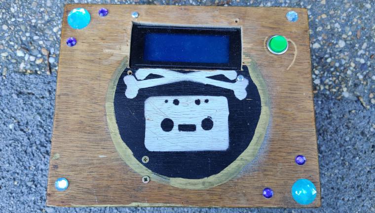
First, I thought about what I wanted the box to do. I wanted it to be some kind of riddle or adventure, so the box needed to be as self explaining as possible. When someone presses the button on top of the box, the display lights up. It shows some message while it is waiting for a GPS fix (e.g. “Reading Map…"). If it doesn’t find a fix, it will show a message to take the box outside. If it does get a fix, it will show the distance to the target in meters as well as the amount of tries that remain. The picture below shows the box from the outside after it was done:

After all the parts arrived, it was time to put it all together. I had some trouble building a lock mechanism. I tried to use a servo motor at first, which was supposed to move a wooden bar left and right to lock and unlock the box. However, the wooden bar got stuck all the time and when I left enough space that it wouldn’t get stuck, it was possible to open the lid enough to peak into the box. So I went back into the city and got a solenoid, which is basically a magnet that pulls a rod. When off, the rod would be pushed forward by a small spring, pushing it into a piece of wood coming from the boxes lid. The solenoid is attached to the side wall of the box, so if it is pushed into the hole in the wood that is attached to the lid, the box is locked. When the box is in the correct location, the microcontroller closes a relay, powering the solenoid. The metal rod is then pulled back out of the hole and the box is unlocked.
I attached the rest of the electronics to the lid of the box, and connected everything using a wild mixture of perfboard and dupont wires. Here’s a badly drawn schematic that I drew:

And here’s how the inside of my lid looked afterwards:

After I wired everything up, it was time for coding. If you want to follow this article, please clone the git repository as this article does not include the complete code. First, we import some libraries that we are going to use and initialize several variables. We also define a custom version of delay that will query the GPS module for new data for a fixed amount of time:
#include <ESP8266WiFi.h>
#include <EEPROM.h>
#include <LiquidCrystal_I2C.h>
#include <TinyGPS++.h>
#include <SoftwareSerial.h>

TinyGPSPlus gps;  // The TinyGPS++ object
SoftwareSerial ss(D7, D6); // The serial connection to the GPS device

// Construct an LCD object and pass it the
// I2C address, width (in characters) and
// height (in characters). Depending on the
// Actual device, the IC2 address may change.
LiquidCrystal_I2C lcd(0x3F, 20, 4);
int counterAddr = 0;
int switchPin = D5;
int relayPin = 3; //RX pin hopefully doesn't go high on boot
float distance = 9999.9;
bool fixTimeOut = false;


const double TARGET_LAT = 50.789639;
const double TARGET_LNG = 6.077338;

// This custom version of delay() ensures that the gps object is being "fed".
static void smartDelay(unsigned long ms){unsigned long start = millis(); do  {while (ss.available()) gps.encode(ss.read());} while (millis() - start < ms);}
Since our code will shut the microcontroller down when it’s done, our whole code will be in the setup() method (and therefore will only be executed once on boot, not repeatedly). We start by initializing the screen and some of our output pins, as well as switching off WiFi to save power. When doing this, I stumbled upon a problem: Some of the ESPs IO pins shortly go HIGH on boot. This is not a problem for some applications, but it would cause our box to unlock shortly everytime the button is pressed if the pin that is connected to the relay behaves like that. I tried a few pins and it worked with pin 3 after I also added a 1k pulldown resistor. We also initialize the software serial connection that we’re going to use to communicate with the GPS module:
void setup() {
  //Shutdown WiFi to save power
  WiFi.mode( WIFI_OFF );
  WiFi.forceSleepBegin();
  delay( 1 );

  digitalWrite(switchPin, LOW);
  digitalWrite(relayPin, LOW);
  pinMode(switchPin, OUTPUT);
  pinMode(relayPin, OUTPUT);
  // The begin call takes the width and height. This
  // Should match the number provided to the constructor.
  lcd.begin(20, 4);
  lcd.init();

  ss.begin(9600);
Next, we need a way to count the amount of tries that have already been spent. Since the microcontroller will reboot, a simple variable won’t do and we need to write it to the ESPs EEPROM. Thanks to the EEPROM library, this is quite simple. If the specified amount of tries has been exceeded, we will show a failure message. Otherwise, we will try to get a GPS fix:
  EEPROM.begin(512);
  int tries = EEPROM.read(counterAddr);

  //Turn on the backlight of the LCD.
  lcd.backlight();

  //If tries > 25, show failure message
  if(tries > 25){
    lcd.clear();
    lcd.setCursor(0, 0);
    lcd.print("Tries exceeded.");
    lcd.setCursor(0, 1);
    lcd.print("Box locked forever.");
    lcd.setCursor(0, 3);
    lcd.print("Contact a pirate!");
  }else{
    lcd.clear();
    lcd.setCursor(0,0);
    lcd.print("Reading map...");
    lcd.setCursor(0, 3);
    lcd.print("Be patient. ");

    //Get position
    smartDelay(200);
    int ms = millis();
    while(gps.satellites.value() < 4 && (millis() - ms) < 120000){
      smartDelay(200);
      lcd.setCursor(17,3);
      lcd.print(gps.satellites.value());
      lcd.print("/4");
      delay(500);
      if(millis() - ms > 115000){
          fixTimeOut = true;
        }
      }
After waiting a maximum of 120 seconds for a GPS fix, we check if we got one. If not, we show some error message. If we got a fix, we will calculate the distance between the box and the target. If the distance is smaller than a predefined threshold (I used 100m), we open the box by setting the relay output pin to HIGH. If we are further away, we will show the distance and the amount of tries to the screen for some time and switch everything off after a while. Additionally, we will show the direction in which the adventurer has to walk if the amount of tries is more than 15, since if they haven’t found by that time their motivation is probably really low:
    if(distance < 100.0){
        lcd.clear();
        lcd.setCursor(0,0);
        lcd.print("You are one");
        lcd.setCursor(0,1);
        lcd.print("bodacious babe!");
        lcd.setCursor(0,3);
        lcd.print("Box is open.");

        digitalWrite(relayPin, HIGH);
        delay(30000);
        digitalWrite(switchPin, HIGH);
      } else {
          String tryString = "/25 tries";

          lcd.clear();
          lcd.setCursor(0,0);
          lcd.print(tries + tryString);

          lcd.setCursor(0,1);
          String distString = "Distance: ";
          String distStringEnd = "m";
          lcd.print(distString + distance + distStringEnd);

          if(tries > 14){
            double courseTo = gps.courseTo(gps.location.lat(), gps.location.lng(), TARGET_LAT, TARGET_LNG);
            lcd.setCursor(0,2);
            lcd.print("Direction: ");
            lcd.print(courseTo);
            lcd.print(gps.cardinal(courseTo));
          }

          tries++;
          EEPROM.write(counterAddr, tries);
          EEPROM.commit();

          delay(10000);
          digitalWrite(switchPin, HIGH);
        }
    }
Now we’re done. However, there are two problems that remain: If we want to reset the tries, we need to flash a different firmware and write 0 to the EEPROM, and if the battery is empty and the box is locked, we need to disassemble the box. To fix both problems, I added a little usb socket. Applying power to the usb socket provides power to the microcontroller, bypassing the battery and the switch. Therefore, if the microcontroller is still on after we triggered the switch, we know it is being powered through the usb port. We then show some gibberish on the screen so that if anyone else tries to connect something to the usb port, they will unplug it before it opens the box. After a while of waiting and printing error messages, we open the box and reset the counter:
  //Print emergency gibberish to to make people unplug usb before box opens
  lcd.clear();
  lcd.setCursor(0,0);
  lcd.print("WARNING:");
  lcd.setCursor(0,1);
  lcd.print("Power too high!");
  lcd.setCursor(0,2);
  lcd.print("Remove USB");
  lcd.setCursor(0,3);
  lcd.print("connection!");

  delay(10000);

  lcd.clear();
  lcd.setCursor(0,3);

  for(int i = 0; i < 80; i++){
    byte randomValue = random(0, 37);
    char letter = randomValue + ' ';
    lcd.print(letter);
    delay(300);
  }

  delay(20000);

  EEPROM.write(counterAddr, 0);
  EEPROM.commit();

  lcd.clear();
  lcd.setCursor(0, 0);
  lcd.print("RESET COUNTER");
  delay(1000);
  lcd.noBacklight();

  delay(10000);

  digitalWrite(relayPin, HIGH);
  delay(20000);
}
That’s it, were done! Time to take our box on a trial adventure!

